NPIV is of the best way to optimize SAN infrastructure in IBM p-Series as well as in IBM i-Series. Normally if you look at highly critical applications actual data resides in SAN. But actual size would be very low I mean total allocated storage space on client ( partition/lpar/dlpar) is minimal it can be less than TB ( Terra Bytes ) in-order to make storage connectivity you need two fiber channel adapters and two SAN switch ports ( considering the redundancy ) it would cost you more. If we calculate total SAN allocation will cost you more. To overcome this kind of requirement and optimizing SAN infrastructure NPIV is the best option.
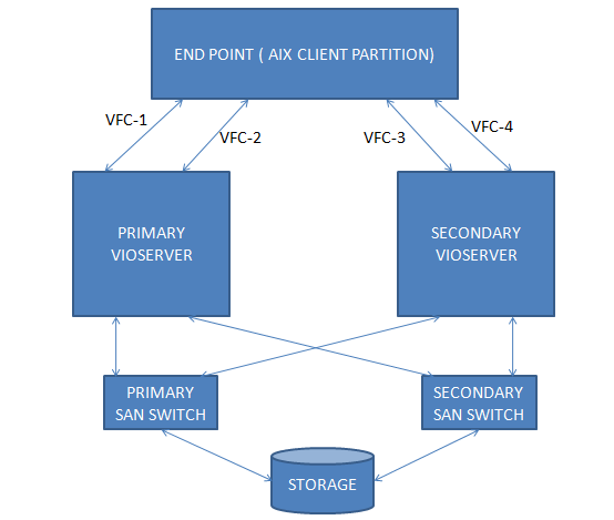
NPIV works as like SCSI adapter which allows multiple client partition can be access to the fiber channel adapter directly which means that actual physical adapter will be present in to VIOSERVERS and logical entity will be created and mapped to client partitions hence in VIOSERVERS physical adapters works in pass-through mode and actual I/O traffic routed through POWER hypervisor.
The virtual fiber channel adapters are shown in client end as like a physical device, I mean which will give you the care make, model and vendor details etc…
Once you create virtual fiber channel adapter two there will be a two WWPN will be created, first one created with starting latter “C” which is used for disk or tape allocation etc …… second one is used for LPM activities.
Limitations & Consideration:-
Use one logical adapter from one physical adapter per client (ensure client gets multiple logical adapter from different physical adapter), incase physical adapter fails actual impact will be minimal if we use multiple physical adapter to create logical adapters.
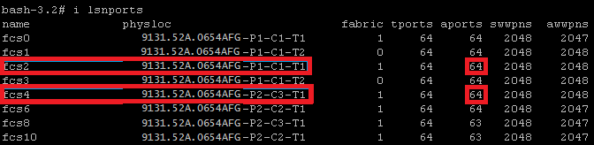
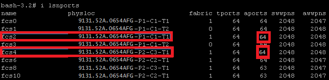
Maximum we can create 64 active virtual fiber channel adapters from one physical fiber channel adapter. (Through lsnports command we can check this limitation in “aports” column)
Before starting NPIV plan ensure Fiber Channel adapter and storage switch is supported for NPIV.
Best Practice Consideration:-
From VIOSERVER_01 (Primary VIOSERVER) we will keep odd numbers first adapter would be 125, second adapter 127 ensure this sequence numbers are not in use.
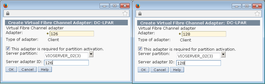
From VIOSERVER_02 (Secondary VIOSERVER) we will keep even number first adapter would be 126 , second adapter 128 ensure this sequence number are not in use.
You have to take care while designing the redundancy part; ensure the redundancy level in VIOSEERVER level as well as SAN switch level as well.
VIOSERVER_01 (Primary VIOSERVER):
Virtual Fiber Channel Adapter: 125 (vfchostX)
Virtual Fiber Channel Adapter: 127 (vfchostX)
Physical Adapter 1:- fcs2 (Fiber Channel cable connected to Primary SAN switch)
Physical Adapter 2:- fcs4 (Fiber Channel cable connected to Secondary SAN switch)
VIOSERVER_02 (Secondary VIOSERVER):
Virtual Fiber Channel Adapter: 126 (vfchostX)
Virtual Fiber Channel Adapter: 128 (vfchostX)
Physical Adapter 1:- fcs2 (Fiber Channel cable connected to Primary SAN switch)
Physical Adapter 2:- fcs4 (Fiber Channel cable connected to Secondary SAN switch)
The above said plan will give you VIOSERVER level redundancy as well as SAN level redundancy.
Considering that VIOSERVER has been installed and NPIV supported Fiber Channel adapter available, client partition profile has been created.
STEP 1: Check attached Fiber Channel adapter has NPIV capability through lsnports command
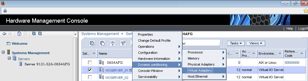
STEP 2: Create Virtual Fiber Channel Adapter ( vfchost ) using DLPAR ( Primary VIOSERVER)
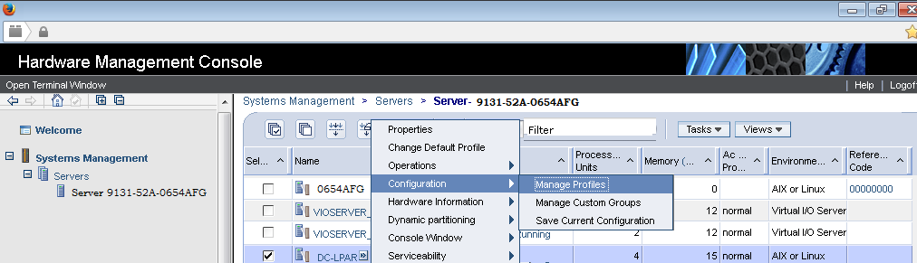
Select VIOSERVER and navigate Dynamic Partitioning —> Virtual Adapters
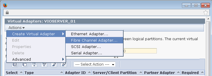
STEP 3: Select Action–>Create Virtual Adapter –>Fiber Channel Adapter
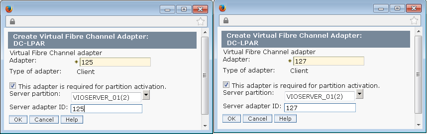
STEP 4: Create fiber channel adapter as planned select the client name DC-LPAR then click ok.
VFC Adapter Number 1: 125
VFC Adapter Number 2: 127
STEP 5: Verify the created fiber channel adapter
![]()
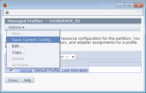
STEP 6: Save the VIOSEREVR configuration
VIOSERVER_01 –> Configuration–>Manage Profile
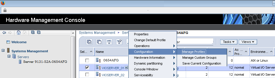
STEP 7: Click ok to Continue

STEP 8: Create Virtual Fiber Channel Adapter ( vfchost ) using DLPAR ( Secondary VIOSERVER)
Select VIOSERVER and navigate Dynamic Partitioning —> Virtual Adapters
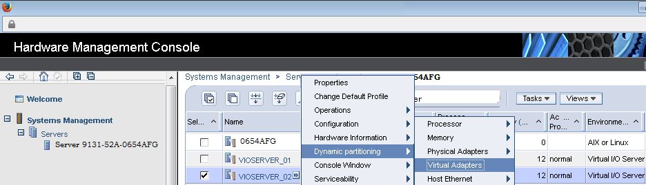
STEP 9: Select Action–>Create Virtual Adapter–>Fiber Channel Adapter
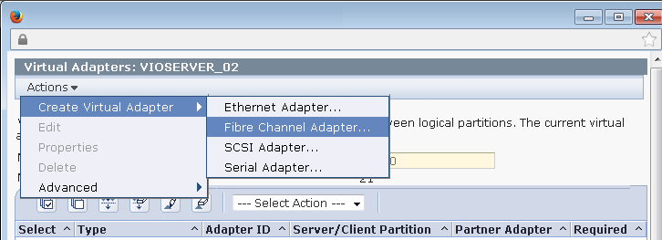
Create fiber channel adapter as planned select the client name DC-LPAR then click ok.
VFC Adapter Number 1: 126
VFC Adapter Number 2: 128

STEP 10: Verify the created fiber channel adapter
![]()
STEP 11: Save the VIOSEREVR configuration
VIOSERVER_02 –> Configuration–>Manage Profile
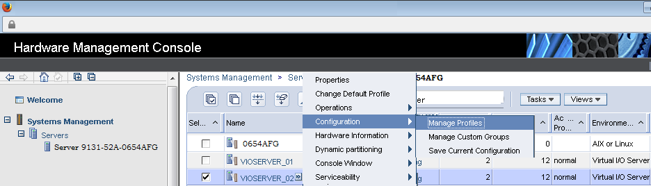
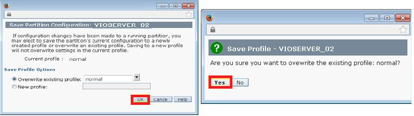
STEP 12: Action–>Save Current Configuration
STEP 13: Click ok to Continue
STEP 14: Check the client partition has the IP address assigned has or not
Partition has IP address then we can create through dlpar otherwise we have to put the entry in profile needs to reflect the change we needs to restart the partition.
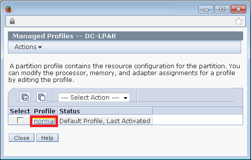
STEP 15: Choose the partition go Configuration –>Manage Profiles to add the virtual fiber channel entry.
STEP 16: Chose Normal Profile.
STEP 17: Go to Action –>Create Virtual Adapter –>Fiber Channel Adapter.
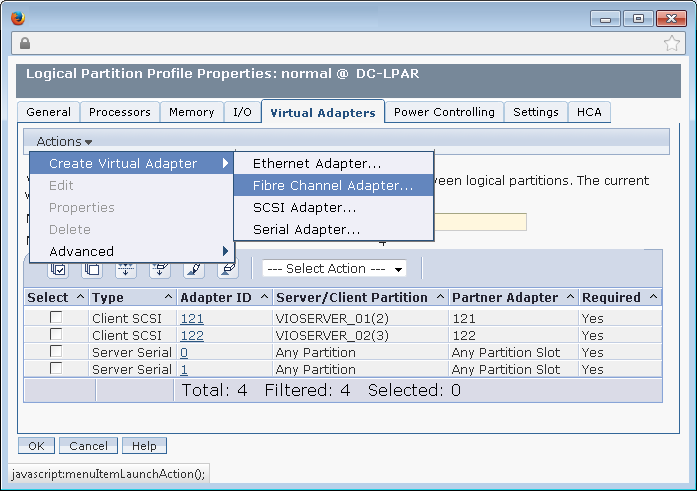
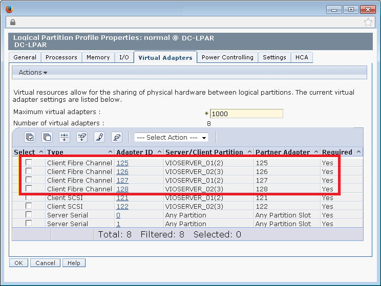
STEP 18: Create four Virtual Fiber Channel Adapter , two from VIOSERVER_01 and two from VIOSERVER_02.

STEP 19: Validate the newly created adapter if everything fine then click of to proceed.
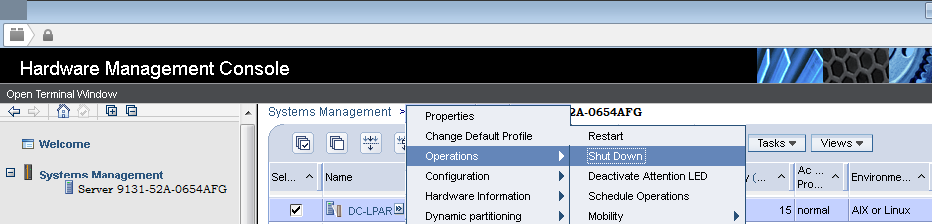
STEP 20: Shutdown and Activate to reflect the configuration changes in LPAR. ( Hence we doesn’t has IP Address assigned on client partition )
Choose the Client LPAR–>Operation–>Shutdown.
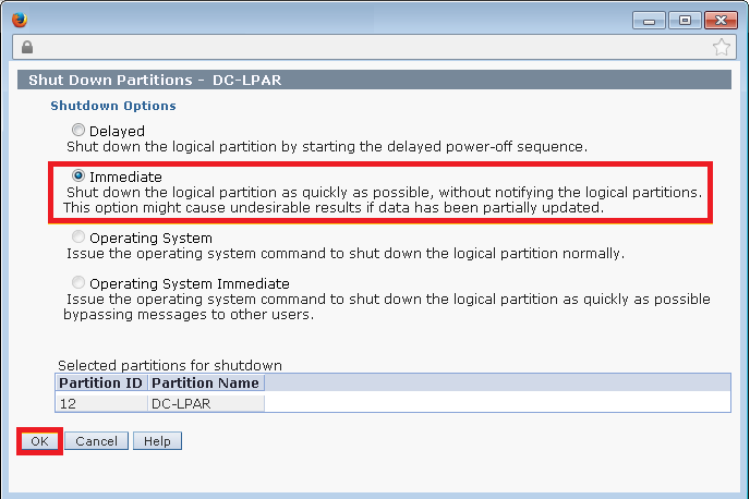
STEP 21: Select Immediate option to Shutdown the client partition.
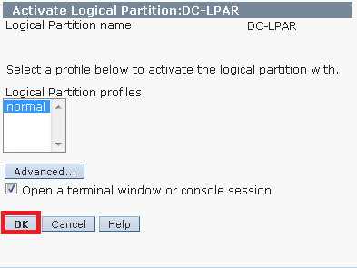
STEP 22: Activate the LPAR Go to Operation–>Action–>Activate–>Profile.
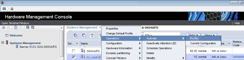
STEP 23: Click OK to Activate Profile.
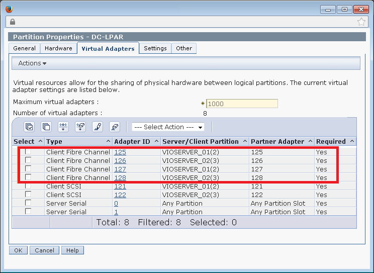
STEP 24: Go to LPAR and Configuration–>Manage Profile–>Virtual Adapters.
Verify Created Virtual FC Adapters.
STEP 25: Login VIOSERVER_01 and set alias for alias i=/usr/ios/cli/ioscli to execute vio’s command.
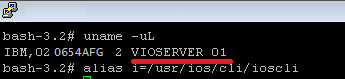
STEP 26: Login VIOSERVER_02 and set alias for alias i=/usr/ios/cli/ioscli to execute vio’s command.
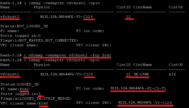
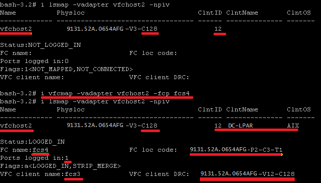
STEP 27: Login the VIOSERVER check your vfchost details through lsmap command
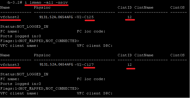
STEP 28: You can see the cable connectivity through checking the fabric column.

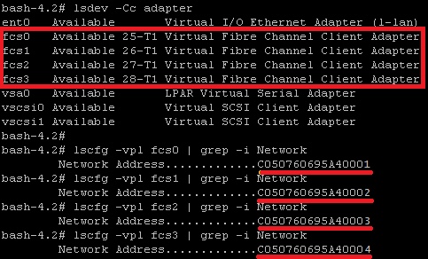
STEP 29: Even you can check through lscfg command to check the vfchosts.
![]()
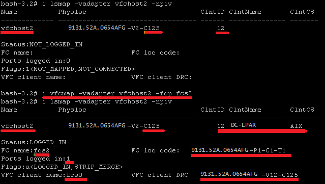
STEP 30: Map your adapters, physical adapters along with logical adapters ( vfchost )
MAP THE PRIMARY ADAPTER FC2
MAP THE SECONDARY ADAPTER FC4
STEP 31: As soon as , mapping done we could see aports number would be reduce from 64 to 63.

STEP 32: Repeat the same procedure for secondary VIOSERVER.
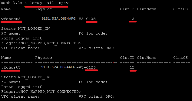
STEP 33: We can see the cable connectivity through checking the fabric column.
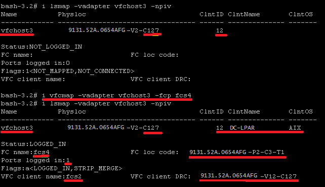
STEP 34: Map your adapters, physical adapters along with logical adapters ( vfchost )
MAP THE PRIMARY ADAPTER FC2
MAP THE SECONDARY ADAPTER FC4
STEP 35: As soon as , mapping done we could see aports number would be reduce from 64 to 63.

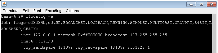
STEP 36: Now login the client partition and list your adapters through lsdev command.
STEP 37: Now you have successfully created the fiber channel adapters , provide your WWPN number to storage team to map storage.
1 Comment
Leave a Comment
You must be logged in to post a comment.
Thanks, this is a wonderful post i ever gone through
Regards
Hemant Singh